The MDM Cables:
| Cinch Interconnect stereo cables MDM 2027. With this cable we use a PE Foam dielectric, and OFC cables, To achieve an affordable cable, which would provide optimum electrical characteristics. We therefore maximise the dielectric value. Careful workmanship assures minimum losses and the reflection factor can almost be eliminated. The excellent values of inductance and capacitance are achieved by ensuring correct geometry within the cable. To eliminate the disturbance from external interference (Magnetic and electrical), we opted for a special graphite shielding in addition to the protection provided by the PVC. | 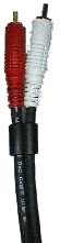 |
| Cinch Interconnect stereo cables MDM 078 These use similar cables as with the MDM 2027, however since the plugs are part of the signal transfer, these are made of a solid non magnetic material, covered by an ABS sleeve. The C 078 plugs are made of a non magnetic material, gold plated and the insulation is made out of Teflon to ensure maximum heat resistance and also best dielectric values. as used for the MDM 078 Cables. | |
| Cinch plug MDM C 078 | 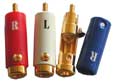 |
| Cinch Interconnect MDM 1402 With this cable we use the same geometry for the signal conductor as with the ACE. The PCOCC conductors are used for the + signal The PE Foam section is slightly larger than used in the 2027 cables and formed of + PE Foam plus XLPE we then use graphite as shielding between the + and – conductor, so that these cannot have any influence at all on each other. The – conductor is then again surrounded by PVC protection and the polyester mash to eliminate any disturbance from the ambience. The plugs are of the gold plated non-magnetic lock type, with an aluminium cover | |
| Cinch Interconnect MDM 1403 symmetric With this cable we use the same geometry for the signal conductor as with the ACE. The PCOCC conductors are used for the + signaland – signal. The PE Foam section is slightly larger than used in the 1402 cables and formed of + PE Foam plus XLPE cotton filler is used to have a perfect geometry between the cables. The ground is then also used as a shielding and cosnists of cable strands and a foil. | |
| Cinch plug MDM C1403 | 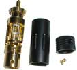 |
| The speaker cables ACE The development of this cable was carried out by using the above mentioned knowledge and of course, like all the MDM cables supported by extensive listening tests. (we worked for three years on this cable) We use two different conductor materials PCOCC and OFC cables in three different sizes. The flow of current is guaranteed with a size of 3.2 mm. To achieve the best and most even geometry of the plus and minus conductors we use a cotton filler. Only in this manner can we achieve the optimum dielectric, capacitance and inductance characteristics To eliminate the ambient factors like magnetic and electrical waves, we use a special graphite shield just inside the sleeve | 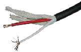  |
Further information about the comcept of MDM Cables
| Electrical diagramm of a cable which are R1 resistance, L1 Inductivity, C1 capacitance, G 1 isolation loss. Dielectric constance (DK): Foamed polyethylene (PE) presents one of the best DK values, which has the best control over the electromagnetic disturbance Resistance: this is related to the diameter of the cable, as a rule, you can take that one mm of diameter will be able to carry appr. up to 10 A Inductance: The outer inductance is reliant on the cable geometry and the magnetic structure of the material used, it is not reliant on frequency and current flow. The inner inductance is largely dependent on the current flow and magnetic fields. Inductance becoming less important with higher frequencies. Capacitance: If the conductor geometry and the dielectric values are carefully chosen, the cable will exhibit good capacitance characteristics. Capacitance and inductance will have an influence on the frequency response of a cable. |  |
| Isolation-loss: The size of the loss factor (TAN) depends again on the dielectric material and surface of the conductor and is also frequency dependent. In general it is good to keep the TAN value as low as possible. | |
| Wave impedance: As we have no standard in our industry (HI FI), our interconnect cables work with 93 ohms. Antennas work with a fixed norm of 75 ohms. The source and receiving units are working with AC signals of a certain impedance. If the impedance of the cable matches the impedance of both units connected, we will see the maximum signal transfer. Bear in mind, that this Wave impedance can, up to 100 MHz, be largely neglected | |
| Reflection factor: Incompatibilities arising in the conductor and isolation “dielectric” of a cable (normally found in cheaper interconnects and speaker cables) can result in reflections at higher frequencies, resulting in a loss of signal strength as well as creating distortions in the signal, it is therefore most important to have an excellent cable surface, together with highly skilled application of the dielectric, in order to achieve tight control of performance in this area | |
| Skin effect: The higher the frequency of the signal being used, the more this signal is pushed to the surface of the cable. The factor penetration being measurable. With copper this penetration factor is 0.00667 mm at 1 MHz. presenting a signal strength of 37% of that found on the surface. This penetration is a factor of 10 less at 100 MHz or 0.00667 mm, hence with a frequency of 10 kHz this factor would be 0.667 mm. It is therefore also important, that the surface of the cables are of extremely good quality. That is why we are using the PCOCC (Ohno Continuous casting) copper in the MDM 1402 interconnect and ACE speaker cables |  |